In the machinery manufacturing industry, it is often necessary to machine cylindrical sections with complex cross-sections, such as Roots vacuum pump rotors. According to the characteristics of the parts of the cylinder, it is easy to process on the planer. In order to accurately process the complex curved cylindrical surface on the planer, we have carried out numerical control transformation on the BC6063 ordinary planer. The numerical control system is a self-designed single-chip microcomputer system. The CPU is 80C196KC. The transmission parts are driven by ball screws and stepper motors. In order to realize the processing of the plane curve, two coordinate linkages are required. The original table longitudinal movement is replaced by stepping motor drive. Considering that the worktable is heavy, the vertical feed movement is realized by the modified tool holder, and the vertical movement of the worktable is reserved for adjusting the processing range of the parts with different specifications. Because the ordinary planer does not have an automatic knife-lifting mechanism, the planer slides over the workpiece during the return stroke, which not only increases the wear of the tool, reduces the tool durability, but also easily scratches the surface of the workpiece. To this end, we use the following measures to improve the tool holder: Remove the original tool lifting part, instead of a fixed tool installation; Each time the tool returns, first automatically raise the knife (in the application set the height of the knife is 0.5mm), in The lifting amount of the tool that the ram moves before the next forward punch; In order to move the tool accurately, the photoelectric encoder disk is connected to the shaft of the stepper motor to precisely control the number of steps of the stepping motor to prevent the motor from moving. The error caused by lost or overshoot. The ram motion position detection and toolholder feed control are based on the cutting properties of the planer. The table or toolholder feed is not allowed during the cutting process, otherwise the tool and workpiece will be damaged. Therefore, the tool holder and table must complete the feed movement during the ram-changed empty knife, including automatic knife raising. In order to detect the position of the ram, two proximity switches are installed on the ram seat. The installation position is shown in Figure 1.
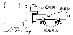
Figure 1 Installation position of the proximity switch
The dashed line in FIG. 1 represents the movement path of the tool carrier. The signals of the proximity switches ST1, ST2 are received by the 80C196KC ports P0.0 and P0.1, and the two signals are output via the OR gate to the high speed input port HSI.0. By adjusting the positions of the two metal blocks, the sequence of signals ST1 and ST2 when the tool passes position I, II, III in the figure is:

The P0 port data is detected in the interrupt handler of HSI.0, and the cyclic instruction assigns a value to a certain set flag unit. It can be seen that the data of the flag unit changes regularly, as shown in Table 1. Thus, the feed control process of the tool holder and the table is: 1) The tool holder automatically raises the tool after the tool over position III; 2) During the ram return process and during the position II, I, the tool holder first descends. After the knife is lifted, the knife holder and the table finish the motion. The automatic feed interrupt service routine processing is: check the content of the mark unit before the interpolation feed; when the unit value is 12H, the tool feed is completed to raise the knife; when the unit value is 21H, the tool post and the worktable finish the feed motion; At the same time, the feed amount of the tool post is compared with the number of pulses from the photoelectric encoder disk to compensate for the errors caused by the lost or overshoot of the stepper motor. Table 1 The data change law of the marker unit The direction of the ram's movement The position of the ram passing P0.1 P0.0 The value of the marker unit goes to II
III 0
1 1
0 01
12 Retreat III
II 1
0 0
1 22
21 into II
III 0
1 1
0 11
12 Retreat III
II 1
0 0
1 22
21 Cycling application After the NC transformation planer is used to process Roots vacuum pump rotor, after the rotor is processed on other machine tools, there is a 3mm margin, and the rough and fine machining is completed by the CNC planer. The tool parameters used are: The sharp corner is about 50°, the main and auxiliary relief angles are about 4° to 8°, and the tip diameter r is 2mm. The application proves that the machining accuracy of the part meets the design requirements of the drawing. After the tool is modified, the roughness of the finishing rotor can reach Ra3.2.
2inch Slackline Kits Playline
Turn any environment into a playground with this Slackline designed as a complete kit specifically for beginners. Featuring static-style material with rubber grip, and an overhead guide line with arm trainer, the PLAY LINE makes learning simple.
Two-piece slackline is fully adjustable and easily installed between trees or other sturdy anchor points.Improve balance skills, core strength, and coordination while having fun.Kit includes slackline, ratchet tensioner, and tree protection
2Inch Slackline Kits Playline,Slackline Kits Playline,Slackline Outdoor Sports,Slackline Highline Kits,Slackline Training
WINNERLIFTING SAFETY EQUIPMENT CO., LTD. , https://www.winnerstrap.com