Compressed air station design method for correctly determining compressed air dew point
The effect of dew point on energy consumption and the method of correctly determining the dew point of compressed air are rarely noticed in the design of compressed air station; the technical performance and use effect of common non-thermal regenerative compressed air drying device and freeze drying device are analyzed; On this basis, the quantitative analysis and comparison of the energy consumption of the non-thermal regenerative compressed air drying device and the non-thermal regenerative composite drying device are emphasized. On the basis of comprehensive analysis and demonstration, the energy-saving design opinions that should be paid attention to when designing compressed air stations are put forward. Compressed air is directly related to the cost of power consumption and the cost of the product. Therefore, how to do well the energy-saving design of the enterprise compressed air station, so that it can meet the production requirements, but also save energy and reduce consumption has become an important part of the design of compressed air stations. This article discusses some aspects of the energy-saving design of compressed air stations.
Reasonable design of air compressor suction pipe position In the past, most of the compressed air stations using piston air compressors, air compressor suction pipe with suction filter, designed only before the suction filter A suction pipe (also equipped with an air suction muffler for environmental protection purposes). Since the 1990s, oil-injected screw air compressors have gradually become the mainstream in the market. However, most of the oil-injected screw-type air compressors have no suction pipes, so some compressed air stations using oil-injected screw air compressors use indoor suction. Indoor inhalation has the following disadvantages: high inspiratory temperature due to heat dissipation of the motor and air compressor, the indoor temperature of the compressed air station is about 35e higher than the outdoor temperature for a long time. Relevant experiments show that the exhaust volume of the compressor is increased every 3e of the inlet temperature. Will be reduced. The use of indoor suction will reduce the displacement of the compressor by 1% and 115%, resulting in wasted energy. In the heating area, the heating load will increase during the heating season. The air intake in the air compressor will be supplemented by the outdoor air. In the heating season, the amount of air to be replenished in the heating season must be heated by the heating facility to the indoor heating temperature. In the cold regions of the north, this heating The temperature difference between indoor and outdoor will be more than 30e. Take a 40Nm air compressor as an example. The working time of the annual heating season is 3000h, and the indoor and outdoor temperature difference is 20e. The annual waste of heat from the heating air compressor can be approximated as follows: In the formula Q) air compressor waste wasted heat, kJ; 1.293) compressed air density, kgPm at the same time, due to heating heating air compressor suction will reduce air compressor displacement by about 5% due to air density reduction, In this case, more energy is wasted than in the non-heating season.
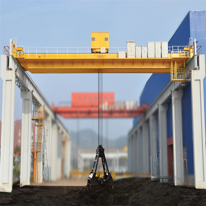
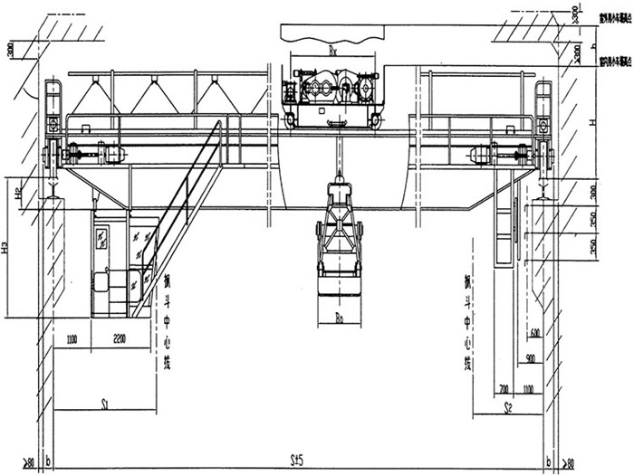
Electric grab Bridge Crane is mainly comprised of box-shaped bridge, grab crab (Grab Bucket), trolley travelling mechanism, cab and electric control system. The load handing device is the grab which is able to capture bulk materials.
The grab cab has switching mechanism and lifting mechanism. The grabs are separately hung over the switching mechanism and lifting mechanism with four steel wire ropes. The switching mechanism drives the grab to close to grab material. When the grab is closed, the lifting mechanism shall be started immediately to hoist the four evenly loaded steel wire ropes. Discharging only needs to start the switching mechanism, which opens the grab to pour materials.
Except the lifting mechanism, the Overhead Crane is basically the same as the bridge crane with hook.

Bridge crane with grab bucket

Specification:
Lifting weight
t
10+10
16+16
25+25
working class
A7
A6
A6
span
mm
25
34
25
33
25
Max. Lifting height
16
16
10
16
10
speed
lifting
m/min
12.6
14.8
16
15.4
travelling
travelling of grab
42.2
42.2
39
48
40
hang beam
travelling of trolley
85.2
85.2
106
101
107
turn round
r/min
1.36
1.36
1.36
1.85
1.4
Max. wheel pressure
KN
190
210
255
260
335
Total power
KW
114.8
128.8
151.3
196
243.5
steel track recommended
QU80
QU100
power source
3 phase A.C 380v 50Hz
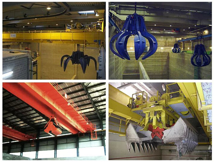
Different grab bucket is available

Grab Crane,Heavy Duty Hydraulic Grab Crane,Grab Bucket Overhead bridge Crane,cranes Grab
Jiangxi Mide Industrial Co., Ltd. , http://www.midecrane.com